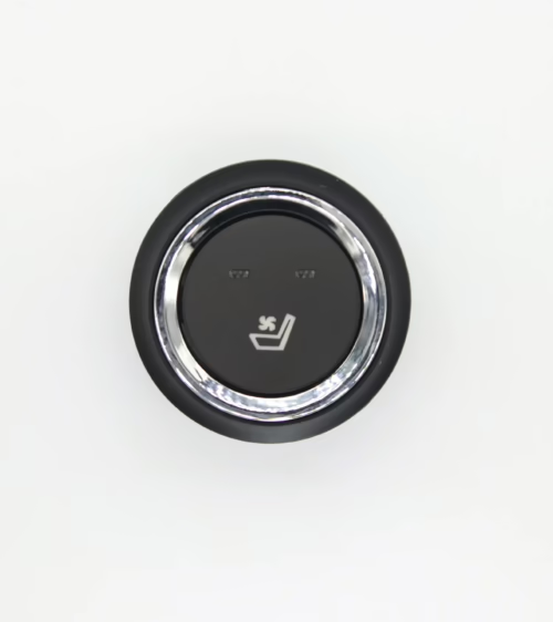
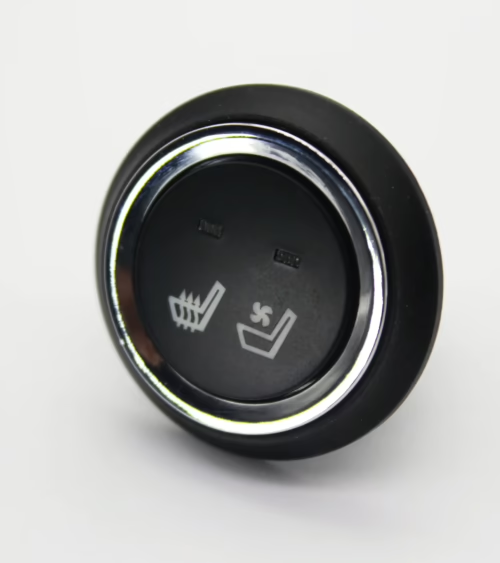
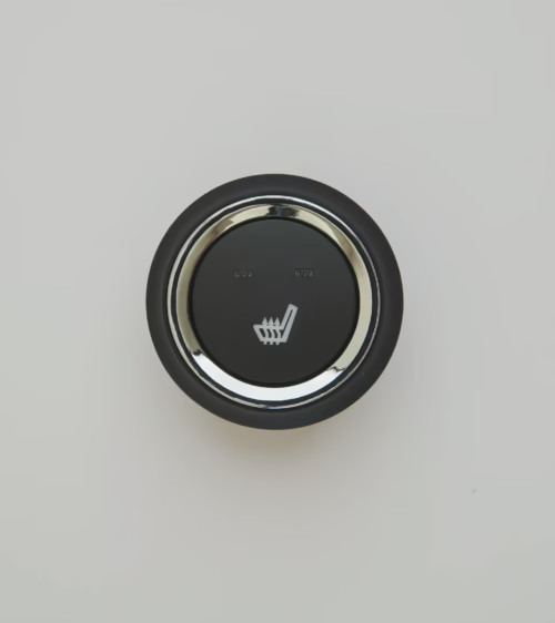
Getting 5 pin seat heater switch wiring right is the difference between a seat heating system that works reliably for a decade and one that fails in a season — or worse, melts a connector.
The five-terminal rocker or paddle switch is the most common control interface in aftermarket and low-volume OEM seat heating systems because it handles switched power, load output, ground, and two separate illumination circuits on a single body.
This guide walks through the pinout, the current path, the wire gauge math, and a seven-step installation and verification sequence used by seat assemblers and upfitters in North America.
What the 5 Pins Actually Do
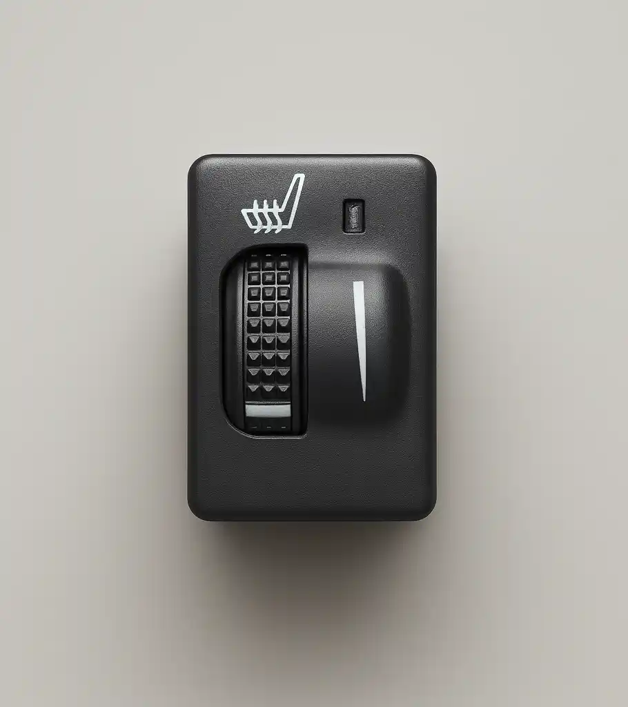
Most 5 pin automotive switches follow the same functional layout regardless of whether the body is a Carling-style rocker, a bezel-mount paddle, or a round push switch. The numbering is usually molded into the switch housing, and the standard assignment is:
- Pin 1 — Backlight (illumination) feed: ties to the vehicle’s parking/dash light circuit so the switch glows at night at reduced brightness.
- Pin 2 — Ground: common return for both the backlight LED and the indicator LED.
- Pin 3 — Load output: feeds the seat heating pad, or the coil of a relay when the pad draws more current than the switch contacts are rated for.
- Pin 4 — Switched or constant 12V input: the main power feed, taken from a fused ignition-switched source.
- Pin 5 — Indicator LED feed: lights up only when the switch is in the ON position, usually internally bridged to pin 3.
Two cautions. First, pin numbering is not universal — some suppliers use a 1/2/3 stack for the contact circuit and 7/8 for illumination, borrowing from the Carling V-series convention. Always verify with a continuity tester before energizing anything.
Second, on a two-stage (high/low) switch, pin 3 may split into two outputs and the switch becomes a 6- or 7-pin part; a true 5 pin switch is a single-stage ON/OFF device with dual illumination.
Reading the Current Path Before You Cut a Wire
A seat heating pad for a standard bucket seat typically draws between 3 and 5 amps per pad at 12V nominal, meaning a bottom-and-back pair pulls 6 to 10 amps.
Many 5 pin rocker switches are rated 20A at 12VDC, which appears to give plenty of headroom — but that rating is for a resistive load at room temperature with a clean connection.
Real automotive service means vibration, thermal cycling, and 14.4V charging-system voltage, which pushes actual draw up by roughly 20 percent over the 12V figure.
The practical rule used in seat assembly:
- if total steady-state load exceeds 10A
- do not switch it directly. Use pin 3 to drive a relay coil (typically under 200 mA) and let the relay’s 30/87 contacts carry the heater current. This keeps the switch contacts cool
- keeps the dash harness light
- localizes any future failure to a $4 relay instead of a trim-mounted switch.
Wire Gauge, Fusing, and Voltage Drop
Undersized wire is the single most common defect found in field-installed seat heating systems.
Voltage drop across the feed wire reduces pad output by the square of the voltage loss — lose 10 percent of voltage and you lose roughly 19 percent of heat output, which customers experience as “the heater barely works.”
- Heater feed (relay to pad): 14 AWG for runs under 8 feet at 10A; 12 AWG beyond that.
- Switch feed and load wire (if no relay): 14 AWG minimum.
- Relay coil trigger from pin 3: 18 AWG is sufficient.
- Illumination circuits (pins 1 and 5): 20 or 22 AWG.
- Ground (pin 2 and pad return): match the feed gauge; never ground through a seat rail bolt that also carries the seat track motor return.
Fuse the circuit at roughly 125 to 150 percent of measured steady-state current — a 10A system gets a 15A fuse, not a 30A one. The fuse protects the wire, not the heater.
Use stranded copper conductors with cross-linked polyethylene (XLPE) or TXL insulation rated to 125°C, since wiring routed under a heated cushion sees elevated ambient temperature for hours at a time.
Basic conductor sizing principles and the underlying relationship between cross-section, current, and heating are covered well in the American Wire Gauge standard, which remains the reference system for North American automotive harness design.
7 Steps to Wire a 5 Pin Seat Heater Switch
The following sequence assumes a 12V negative-ground vehicle, one pair of heating pads per seat, and a relay-driven layout.
- Step 1 — Disconnect the battery negative terminal. Seat systems sit near side-airbag squibs and occupancy sensors; a stray probe on a live harness is an expensive mistake. Wait at least three minutes for capacitor discharge before working near the seat.
- Step 2 — Confirm the pinout with a multimeter. Set to continuity, place one probe on pin 4 and the other on pin 3, and toggle the switch. Continuity in the ON position confirms those two are your contact pair.
- Then verify pin 5 goes live with pin 3 and pin 2 is common to the LED returns.
- Step 3 — Establish the power source. Tap an ignition-switched circuit, never a constant-hot one. A seat heater left on with the engine off will flatten a battery in a few hours and, in a pad with a failed thermostat, creates a genuine fire risk.
- Add an inline fuse within 6 inches of the tap point.
- Step 4 — Wire the control side. Fused switched 12V to pin 4. Pin 3 to the relay terminal 86. Relay terminal 85 to chassis ground. This is the low-current loop.
- Step 5 — Wire the load side. Battery positive (through its own fuse) to relay terminal 30. Relay terminal 87 to the heating pad positive. Pad negative to a dedicated chassis ground point — scraped to bare metal, star washer, dielectric grease applied after torquing.
- Step 6 — Wire illumination. Pin 1 to the dash/parking light circuit so the switch outline glows with the headlights. Pin 2 to the same clean ground as the switch. Pin 5 is normally internally fed; if your switch requires an external feed, bridge it to pin 3.
- Step 7 — Route, secure, and test. Keep harness runs away from seat track pinch points and slider rails, leave a service loop at the seat base for full fore/aft travel, and secure every 6 to 8 inches. Reconnect the battery and proceed to verification.
Grounding Mistakes That Cause Intermittent Faults
Roughly half of all seat heater warranty returns that test good on the bench are ground-path problems. The failure signature is distinctive:
- the heater works for a few minutes
- then fades
- or the indicator LED dims when the blower motor runs. Both point to a shared ground with too much resistance.
Give the heater load its own ground stud. Do not daisy-chain the pad return through the switch ground at pin 2 — the LED circuit is milliamps and the pad is amps, and putting them on the same conductor makes the indicator brightness track heater current. Measure ground quality directly:
- with the heater running
- put your meter between the pad’s negative terminal and the battery negative post. Anything above 0.2V indicates excess resistance in the return path that needs correcting.
Testing and Commissioning the Circuit
Run these four checks before reinstalling trim, in this order:
- Static continuity: with the battery still disconnected, confirm no continuity between the heater feed and chassis ground. Continuity here means a pinched wire.
- Current draw: clamp an ammeter on the pad feed with the system on. Reading should land within 15 percent of the pad’s rated draw. High reading suggests a shorted turn in the heating element; low suggests an open segment or excessive voltage drop.
- Voltage at the pad: measure across the pad terminals under load with the engine running. You want within 0.5V of system voltage. A larger gap is a wiring problem, not a pad problem.
- Thermal soak: let the system run 20 minutes and check the surface temperature at several points on the cushion. Target surface temperature on a finished seat is typically 38 to 42°C. Verify the thermostat or NTC thermistor cycles the circuit rather than letting it climb indefinitely.
Choosing the Right Switch for the Application
Switch selection is dictated by three things:
- the trim aperture you have to fill
- the illumination color your interior uses
- the contact rating relative to your load. For OEM seat programs
- the switch also has to survive the customer’s validation cycle — typically 50,000 to 100,000 actuations plus salt spray and thermal shock. Cheap switches pass the first 10,000 cycles and fail on contact erosion afterward.
If you are specifying for a production seat rather than a one-off install, prioritize a switch with silver-alloy contacts, a sealed body rated IP54 or better at the front face, and a detent that gives clear tactile feedback so the operator knows the state without looking.
Our seat heater switch catalog covers standard rocker, paddle, and round-bezel formats in both single-stage and high/low configurations, with pinouts documented for each part number.
Frequently Asked Questions
Can I wire a 5 pin seat heater switch without a relay? Yes, if total load is under about 10A and the switch is genuinely rated 20A at 12VDC. For a single pad drawing 4A, direct switching is fine.
For a bottom-plus-back pair, or any two-seat system sharing one switch, add the relay. The relay costs a few dollars and moves the heat away from a component buried in your trim.
Why does my indicator LED stay lit when the switch is off? Almost always a swap between pin 1 and pin 5. Pin 1 is the constant backlight tied to the dash lights; pin 5 is the state indicator tied to the load circuit.
If the always-on glow is on the wrong element, move those two wires. If both stay lit, check for a backfeed through a shared ground.
Does the wiring change for a 24V truck system? The topology is identical, but the switch and relay must be rated for 24V, current at a given wattage is halved so wire gauge can drop one step, and the illumination LEDs need the correct series resistor for 24V — running a 12V LED switch at 24V will destroy it within seconds.
Confirm the voltage rating stamped on the switch body before installation.
Get the Right Parts the First Time
Lucky Driver Inc. supplies seat heating pads, switches, control modules, and ventilation systems to OEM seat manufacturers and aftermarket distributors across North America, with documented pinouts, current ratings, and validation data for every part we ship.
If you are building a seat program, retrofitting a fleet, or stocking a distribution channel, you can browse our full range of seat heating products or contact our engineering team for application support on wire gauge, relay selection, and thermostat placement.
Tell us the seat, the voltage, and the target surface temperature, and we will spec the system.
Related Articles
- 3 Position Seat Heater Switch: 7 Specs to Check (2026 Guide)
- Seat Heater High Low Switch Wiring: 7 Steps (2026 Guide)
- Seat Heater Amp Draw: 7 Numbers to Check (2026 Guide)
- 24V Seat Heater for Trucks: 7 Specs to Get Right (2026)
- 12V Seat Heater Pad: 7 Specs Every Buyer Must Check (2026)
Frequently Asked Questions About 5 pin seat heater switch wiring
Procurement engineers evaluating 5 pin seat heater switch wiring for OEM programs regularly ask the following questions. Answers cover specification, compatibility, certification, and sourcing for 5 pin seat heater switch wiring requirements.
What voltage ratings are available for 5 pin seat heater switch wiring?
Standard 5 pin seat heater switch wiring configurations support 12 V DC for passenger vehicles and 24 V DC for commercial trucks. Selecting the correct 5 pin seat heater switch wiring voltage at the design stage eliminates harness rework later.
Lucky Driver maintains 5 pin seat heater switch wiring inventory in both ratings for same-week shipment.
Which certifications apply to 5 pin seat heater switch wiring production?
5 pin seat heater switch wiring assemblies entering OEM programs typically require UL recognition, REACH compliance, and RoHS documentation. Lucky Driver holds certification records for every 5 pin seat heater switch wiring variant and includes copies with sample and production shipments.
How is watt density specified for 5 pin seat heater switch wiring?
Watt density for 5 pin seat heater switch wiring is expressed in W/cm² and ranges from 0.04 to 0.12 depending on heat-up time requirements. Lower watt density 5 pin seat heater switch wiring designs improve element longevity, while higher values suit cold-climate applications.
Lucky Driver engineering reviews 5 pin seat heater switch wiring requirements and recommends watt density based on your seat platform.
What connector families are used with 5 pin seat heater switch wiring?
5 pin seat heater switch wiring harnesses are available with Molex, TE Connectivity, and Delphi connector families. Matching the 5 pin seat heater switch wiring connector to the vehicle harness reduces assembly time and eliminates adapter cables.
Specify your harness format when requesting a 5 pin seat heater switch wiring quote from Lucky Driver.
What is the lead time for 5 pin seat heater switch wiring samples?
5 pin seat heater switch wiring samples from Lucky Driver’s North American warehouse ship within 3 to 5 business days for standard configurations. Custom 5 pin seat heater switch wiring variants with modified pad geometry or connector pinouts require 4 to 6 weeks.
Contact Lucky Driver to confirm 5 pin seat heater switch wiring availability before submitting your engineering schedule.