Getting seat heater high low switch wiring right is the difference between a seat that reaches comfort temperature in four minutes and one that trips a thermal fuse, scorches foam, or quietly drains a battery overnight.
In our experience supplying seat heating hardware to OEM seat builders and aftermarket distributors, most field failures are not dead heating elements at all — they are wiring errors at the switch:
- a high-stage leg landed on the wrong terminal
- a shared ground carrying both stages
- or an illumination feed tapped from the heater supply. This guide explains how two-stage control actually works
- the three switching architectures used in production vehicles
- a seven-step wiring procedure
- the fault patterns that show up on a bench meter.
1. What “High” and “Low” Actually Mean Electrically
A heated seat has no throttle. The carbon-fiber or resistance-wire element is a fixed resistance, and the only variables available are applied voltage, circuit resistance, and duty cycle.
“High” and “Low” are therefore not settings in any software sense — they are two different electrical states of the same element set.
Take a typical 12V cushion pad measuring 3.0 ohms. At full battery voltage it draws roughly 4.0 amps and dissipates about 48 watts. To produce a low stage, the circuit must either raise total resistance, reduce applied voltage, or reduce average power over time.
A series ballast that doubles circuit resistance to 6.0 ohms halves current to 2.0 amps but cuts power to roughly 24 watts — a genuine 50% reduction in heat output. That relationship matters:
- power scales with the square of current
- so small resistance changes move surface temperature more than installers expect.
2. The 3 High/Low Switching Architectures
Nearly every two-stage seat heater on the road uses one of three approaches, and identifying which one you have determines the entire wiring plan.
- Dual-circuit switching. The cushion and backrest pads are wired as two independent element circuits. Low energizes one circuit; High energizes both in parallel. This is the most common aftermarket layout and requires a switch rated for the full combined current on the High position.
- Series/parallel switching. Two elements sit in series for Low and are reconfigured in parallel for High, giving a 4:1 power ratio. It is elegant and uses no ballast resistor, but it demands a double-pole switch with a genuine changeover contact, not a simple two-position rocker.
- Module-controlled (low-current signal). The switch carries only a milliamp-level logic signal to a control module, which drives the element through a MOSFET using pulse-width modulation. This is the OEM standard on modern vehicles because it allows closed-loop temperature control and staged power-down.
Do not mix architectures. Wiring a load-carrying switch into a module-driven harness sends full element current through contacts sized for signal duty, and the contacts will weld.
3. Reading the Switch Connector Pinout
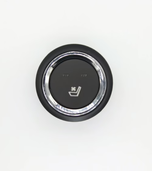
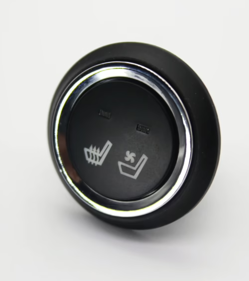
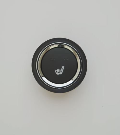
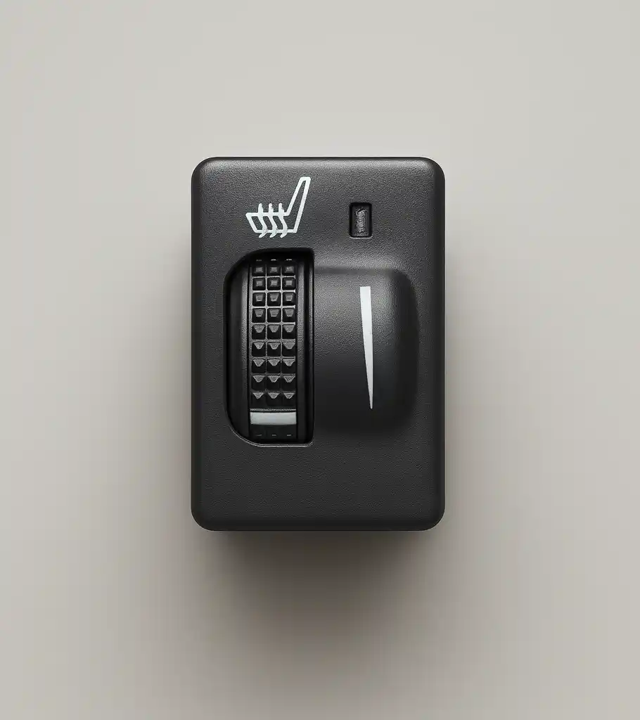
A two-stage rocker or paddle switch typically presents five to seven terminals, and the labeling is rarely printed in a useful place. On a standard five-terminal unit you will find:
- battery input (B+)
- Low output
- High output
- ground for the indicator LEDs
- a backlight feed that follows the vehicle’s park-lamp circuit.
Verify every pin with a meter before connecting anything. Set the meter to continuity, place one probe on the suspected B+ terminal, and cycle the switch through Off, Low, and High.
The terminal that shows continuity to B+ only in Low is your Low output; the terminal that shows continuity only in High is the High output.
If one terminal shows continuity in both positions, you are holding a progressive switch where High adds a second circuit rather than transferring it — a meaningful difference that changes your fuse sizing.
When sourcing a replacement, match the contact arrangement rather than the faceplate; our seat heater switch catalog lists contact configuration and current rating for each part so the electrical behavior is known before installation.
4. Seven Steps to Wire a High/Low Seat Heater Switch
- Step 1 — Disconnect the battery negative terminal. Seat harnesses often route near airbag squib connectors, and a disturbed occupant-detection circuit will set a permanent fault code.
- Step 2 — Measure element resistance cold. Record cushion and backrest values separately. A reading more than 10% off the datasheet indicates a damaged element that no wiring will fix.
- Step 3 — Establish a fused supply. Pull power from a switched ignition source through a dedicated fuse, sized per Step 5. Never feed a heater from an accessory circuit already loaded with other devices.
- Step 4 — Install the relay if the switch is not load-rated. The switch then drives the relay coil, and the relay carries element current from the fuse to the pads.
- Step 5 — Land the Low and High outputs. Confirm with the meter one final time. Reversed outputs produce a seat that runs hottest on the Low indicator — a safety issue, not just an annoyance.
- Step 6 — Run a dedicated ground. Take the element ground to a clean chassis stud under the seat rail, not to the seat frame slider or a shared ground already serving a motor.
- Step 7 — Test at both stages with a clamp meter. Verify current draw matches calculated values, then let the seat run fifteen minutes and confirm the thermostat cycles.
5. Wire Gauge, Fusing, and Voltage Drop
Two-stage heaters are frequently under-wired because installers size conductors for the Low stage they tested first. Size everything for the High stage plus a margin.
For a 12V system drawing 8 amps on High across a typical 10-foot round-trip run from the fuse box to the seat, 16 AWG copper yields roughly 0.5V of drop — acceptable.
Stretch that run to 16 feet or add a corroded splice and the drop climbs past 1V, which costs about 8% of available heating power and shifts the perceived warm-up time by more than a minute. Use 14 AWG for runs over 12 feet or currents above 10 amps.
Fuse at approximately 125% of measured High-stage current, rounded to the next standard value: a 8.0A load takes a 10A fuse. Fusing at 20A “to be safe” is the opposite of safe — it allows a chafed conductor to heat the seat foam indefinitely without interrupting the circuit.
6. Thermostat and Thermal Fuse Placement
A high/low switch sets power level; it does not limit temperature. That job belongs to a bimetallic thermostat wired in series with the element, plus a one-shot thermal fuse as the backup.
The thermostat must sit between the element and the seat surface, centered in the occupant contact zone, with its sensing face toward the trim cover. Placed under the element or off to the side, it reads pad backside temperature and cycles late, allowing surface temperature to overshoot.
Typical cushion thermostats open near 40–45°C and reset with roughly 10°C of hysteresis; leather trim generally uses the lower band because leather conducts heat to the skin faster than cloth.
Wire the thermal fuse in the main element leg so it protects both stages. A thermal fuse installed downstream of the High branch only will not protect the seat when the fault occurs in Low.
7. Diagnosing Common Two-Stage Wiring Faults
Most complaints resolve to a small set of repeatable causes:
- High works, Low does nothing. Usually an open ballast resistor or a broken series link in a series/parallel layout. Measure resistance across the switch in the Low position.
- Both stages produce identical heat. The Low and High outputs are bridged, often by a crushed connector or a misplaced jumper. Element current will read identical on a clamp meter in both positions — that confirms it.
- Seat heats, then quits after a few minutes, and returns the next day. Classic thermostat cycling combined with an undersized supply, or a thermostat mounted too close to the element.
- Indicator LED lights but no heat. The switch logic side is powered while the load side is open — a relay coil energizing with failed relay contacts, or a blown element fuse.
- Voltage drop under load. Measure at the pad connector, not at the fuse box, with the seat running on High. Anything over 1V indicates connector or ground trouble.
When an element itself is confirmed open, replace the pad rather than splicing the carbon or wire filament; a repaired element creates a local resistance change and a hot spot.
Matching pads, switches, thermostats and modules from one source avoids mismatch, and you can browse our full range of seat heating products to keep the whole circuit consistent.
Frequently Asked Questions
Can I add a high/low switch to a single-stage heated seat? Yes, if the element can tolerate the change. The simplest method is inserting a ballast resistor in series for the Low position, sized to roughly double circuit resistance.
Choose a resistor rated for at least twice the calculated dissipation and mount it on metal away from foam and trim, because it converts the removed heat into its own heat.
Does the switch need a relay? If the switch is rated at or above the High-stage current with margin, no. If the rating is unclear, or if High exceeds 10 amps, use a relay.
Relays also let you run heavy-gauge wire directly from the fuse box to the seat and keep only a light trigger wire routed through the cabin.
Why does my seat feel hotter on Low than High? Almost always reversed outputs at the switch, or a progressive-contact switch wired as a changeover type. Verify continuity per position with a meter before assuming the element or thermostat is at fault.
Get the Right Switch and Pad for Your Build
Two-stage seat heating is straightforward when the switch contact arrangement, element resistance, conductor size, fuse rating, and thermostat placement are specified together rather than assembled from whatever is on the shelf. Lucky Driver Inc.
supplies seat heating pads, high/low switches, control modules, and ventilation systems to OEM seat manufacturers and aftermarket distributors across North America, with documented resistance values, current ratings, and contact configurations for every part. Contact Lucky Driver Inc.
with your voltage, pad dimensions, and target power, and our team will specify a matched set that wires cleanly the first time.
Related Articles
- Seat Heater Amp Draw: 7 Numbers to Check (2026 Guide)
- 24V Seat Heater for Trucks: 7 Specs to Get Right (2026)
- 12V Seat Heater Pad: 7 Specs Every Buyer Must Check (2026)
- Seat Heater Element Resistance: 7 Facts for Buyers (2026)
- Carbon Fiber Seat Heater Pad: 7 Facts Buyers Need (2026)
Frequently Asked Questions About seat heater high low switch wiring
Procurement engineers evaluating seat heater high low switch wiring for OEM programs regularly ask the following questions. Answers cover specification, compatibility, certification, and sourcing for seat heater high low switch wiring requirements.
What voltage ratings are available for seat heater high low switch wiring?
Standard seat heater high low switch wiring configurations support 12 V DC for passenger vehicles and 24 V DC for commercial trucks. Selecting the correct seat heater high low switch wiring voltage at the design stage eliminates harness rework later.
Lucky Driver maintains seat heater high low switch wiring inventory in both ratings for same-week shipment.
Which certifications apply to seat heater high low switch wiring production?
seat heater high low switch wiring assemblies entering OEM programs typically require UL recognition, REACH compliance, and RoHS documentation. Lucky Driver holds certification records for every seat heater high low switch wiring variant and includes copies with sample and production shipments.
How is watt density specified for seat heater high low switch wiring?
Watt density for seat heater high low switch wiring is expressed in W/cm² and ranges from 0.04 to 0.12 depending on heat-up time requirements. Lower watt density seat heater high low switch wiring designs improve element longevity, while higher values suit cold-climate applications.
Lucky Driver engineering reviews seat heater high low switch wiring requirements and recommends watt density based on your seat platform.
What connector families are used with seat heater high low switch wiring?
seat heater high low switch wiring harnesses are available with Molex, TE Connectivity, and Delphi connector families. Matching the seat heater high low switch wiring connector to the vehicle harness reduces assembly time and eliminates adapter cables.
Specify your harness format when requesting a seat heater high low switch wiring quote from Lucky Driver.
What is the lead time for seat heater high low switch wiring samples?
seat heater high low switch wiring samples from Lucky Driver’s North American warehouse ship within 3 to 5 business days for standard configurations. Custom seat heater high low switch wiring variants with modified pad geometry or connector pinouts require 4 to 6 weeks.
Contact Lucky Driver to confirm seat heater high low switch wiring availability before submitting your engineering schedule.