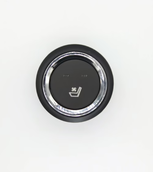
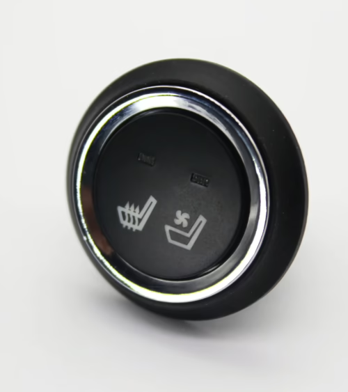
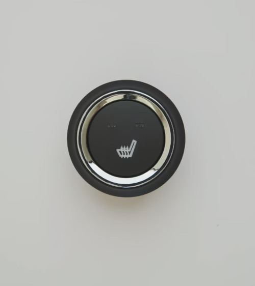
What Is an Integrated Seat Heating Ventilation Module?
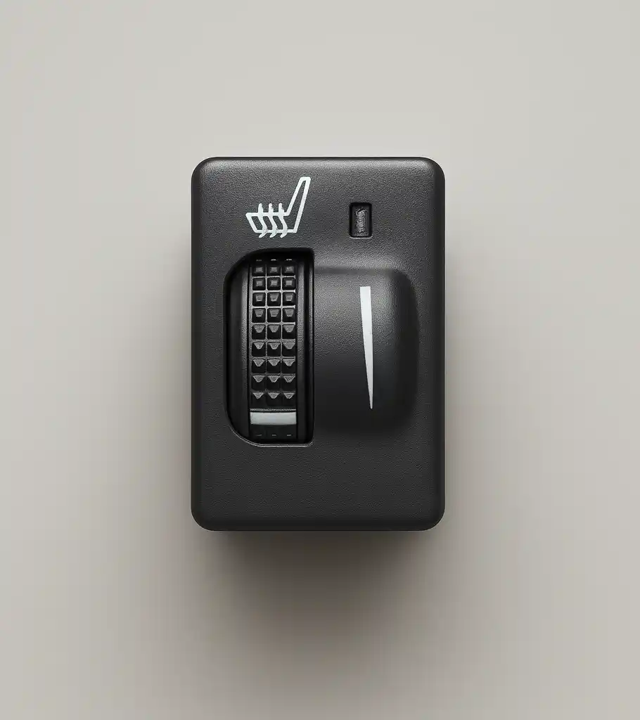
An integrated seat heating ventilation module combines two thermal comfort functions—resistive heating and active airflow—into a single assembly mounted within a seat cushion or backrest. Unlike split systems that wire separate heating pads and blower assemblies to independent controllers, an integrated module shares a common control board, a unified connector harness, and a single ECU interface.
This architecture reduces total component count, simplifies harness routing, and allows the seat climate zone to respond to temperature, fan speed, and occupancy signals through one data channel. The result is a more compact installation, faster calibration cycles during seat assembly, and a cleaner diagnostic surface when troubleshooting in the field.
How the Dual-Function Thermal System Works
The module operates in three modes: heating only, ventilation only, and simultaneous heating-with-ventilation. In heating mode, a resistive heater mat draws current from the vehicle’s 12 V or 48 V bus and converts electrical energy to radiant heat that conducts through seat foam and cover material.
In ventilation mode, a brushless DC centrifugal blower forces air through a perforated distributor plate and out through the seat cover’s perforation pattern, either expelling body-surface humidity or drawing conditioned cabin air downward through the cushion depending on blower orientation.
When both functions run simultaneously, the controller modulates heating power to compensate for the cooling effect of airflow. A closed-loop algorithm reads a thermistor embedded in the heater mat and adjusts pulse-width modulation (PWM) duty cycle to hold a target surface temperature—typically 36–42 °C at 23 °C ambient—while the blower maintains its commanded speed.
This thermal balancing is the technical distinction between a true integrated module and two independently operated subsystems sharing a mounting location.
Core Components and Internal Architecture
A production-grade integrated seat heating ventilation module contains the following elements working in coordination:
- Heater mat assembly: A laminated pad with resistive wire or carbon-fiber traces sandwiched between non-woven fabric layers. Resistance values range from 1.8 Ω to 4.5 Ω depending on target wattage, typically 45–80 W per zone.
- BLDC blower: A 12 V radial fan drawing 3–8 A at full speed, operating between 1,500 and 4,500 RPM. Brushless designs are preferred for lifespan targets exceeding 10,000 operating hours.
- Control PCB: Houses a PWM driver for the heater mat, a MOSFET or relay stage for the blower motor, a microcontroller or dedicated ASIC, an NTC thermistor input circuit, and a LIN or CAN transceiver for vehicle bus communication.
- Distributor plate: A rigid or semi-rigid plastic panel with a honeycomb or radial channel pattern that diffuses blower output evenly across the cushion or backrest surface without creating localized cold spots.
- Occupancy sensor input: Accepts a signal from the seat’s occupant classification system to disable heating and ventilation on unoccupied seats, reducing current draw and extending component life.
- Sealed connector stub: A multi-pin weatherproof connector—typically 8–12 pins—carrying power, ground, LIN or CAN, thermistor feedback, and occupancy lines through a single mating interface.
Key Performance Specifications to Evaluate
Engineers qualifying an integrated seat heating ventilation module for a vehicle program measure performance across several parameters:
- Warm-up time: Best-in-class modules reach 36 °C in under 3 minutes at 0 °C ambient on a 12 V nominal supply.
- Surface temperature uniformity: OEM benchmark for premium seating is a delta below 5 °C across the full cushion area under steady state.
- Airflow rate: Effective moisture removal typically requires 25–60 liters per minute at the cover surface, depending on perforation density and foam porosity.
- NVH performance: Blower radiated noise must remain below 35 dB(A) at 1 meter in a 40 dB(A) cabin baseline.
- Operating voltage range: Modules must function normally from 9 V to 16 V on 12 V architecture or 36 V to 54 V on 48 V mild hybrid platforms.
- Overheat protection: A secondary NTC or thermal fuse must interrupt heater current if mat surface exceeds 65 °C to satisfy FMVSS and ECE R17 thermal safety requirements.
OEM Integration vs. Aftermarket Retrofit
OEM seat manufacturers integrating a module during production can design the foam cavity, distributor plate geometry, and cover perforation pattern around the module’s airflow characteristics from the start. This co-development process typically takes 12–18 months from concept to production validation, including thermal mapping, durability cycling, and EMC testing under IATF 16949-compliant quality systems.
Aftermarket integrators work within existing seat geometry, which introduces three constraints. First, the foam cavity may not have sufficient depth for a standard-thickness distributor plate, requiring a low-profile blower or a custom foam insert. Second, existing non-perforated covers sharply reduce ventilation effectiveness unless the cover is replaced or mechanically punched.
Third, electrical integration must tap an existing fuse block and, on newer platforms, communicate with LIN-based body control modules through a standalone gateway rather than through OEM factory software.
For aftermarket use cases, modular designs with adjustable mounting flanges and a standalone controller that accepts a simple 3-speed switch input—rather than requiring LIN bus configuration—are the most practical choice. They operate independently without BCM reprogramming and can be validated against a wider range of host vehicles.
Wiring, Control Logic, and Field Diagnostics
LIN-based integrated modules follow the LIN 2.1 or LIN 2.2A specification as slave nodes under the BCM or climate control module master. The seat climate LIN frame typically carries set-point temperature (5-bit), fan speed (3-bit), operating mode (2-bit), and diagnostic status fields. The module responds with actual mat temperature, blower RPM feedback, and fault codes covering open-circuit heater, blower overcurrent, thermistor failure, and overheat shutdown events.
For field diagnostics, measure heater mat resistance cold — it should match the spec value within ±10%. Check blower free-spin RPM with an oscilloscope on the BLDC feedback line. Verify thermistor resistance at a known ambient temperature using the manufacturer’s NTC curve. Most field failures fall into three categories: broken heater traces from repeated seat flexion, blower bearing wear in high-ventilation markets, and PCB solder joint fatigue from thermal cycling.
Materials Compliance and Safety Standards
Heater mat substrates are typically polyester non-woven fabric rated to 150 °C continuous, with resistive element insulation validated to 300 V dielectric strength. The module assembly must satisfy FMVSS 302 flammability requirements, ECE R10 for electromagnetic compatibility, and UL 1995 or its automotive equivalent for heating equipment. Blower housings use glass-filled PA66 (nylon) for dimensional stability at temperatures up to 85 °C.
Modules sold into European markets must comply with the End-of-Life Vehicles Directive (ELV 2000/53/EC), restricting lead, mercury, cadmium, and hexavalent chromium. Tier-1 seat manufacturers increasingly require REACH SVHC substance declarations as part of supplier qualification, and modules intended for North American OEM programs must carry a PPAP submission package including material and performance data records.
Frequently Asked Questions
Can an integrated seat heating ventilation module be retrofitted into any existing seat?
Technically yes, but three factors determine practical success: foam cavity depth (minimum 18–22 mm for most blower assemblies), seat cover perforation density for airflow to reach the occupant, and available current at the seat zone fuse. Non-perforated leather covers need replacement or mechanical punching to deliver meaningful ventilation. Heating alone is far easier to retrofit and works in nearly any seat without structural modification.
What is the difference between a PTC heater element and a carbon-fiber element?
A PTC (positive temperature coefficient) ceramic element self-limits its power output as it reaches operating temperature, reducing overheat risk inherently rather than relying solely on controller logic. Carbon-fiber and resistive wire elements maintain a flat resistance curve and deliver consistent wattage regardless of surface temperature, producing faster initial warm-up but requiring the controller to manage thermal cutoff actively.
Carbon-fiber elements are lighter and more conformable for curved seat geometries; PTC ceramics are common in cost-sensitive trim levels where the self-limiting characteristic simplifies the controller design.
What is the typical service life of an integrated seat heating ventilation module?
OEM-grade modules are validated to 10 years or 150,000 km under duty cycles representative of the target market. Field data from North American aftermarket programs indicates a mean time between failures of 6–8 years under average use, with heater mat trace breaks near seat fold points being the most common failure mode in low-back and split-fold seat designs.
Source Integrated Seat Heating Ventilation Modules from Lucky Driver Inc.
Lucky Driver Inc. supplies seat heating pads, heater switches, control modules, and integrated seat heating ventilation modules to OEM seat manufacturers and aftermarket distributors across North America. Whether your program requires a validated off-the-shelf module for a retrofit application or a co-developed solution engineered around a new seat platform, Lucky Driver’s technical team can support your project from initial specification through production qualification.
Reach out to Lucky Driver Inc. to request samples, technical data sheets, or a custom sourcing consultation for your seat climate program.
Integrated Seat Heating Ventilation Module: Sourcing Guide
An integrated seat heating ventilation module consolidates the heater PWM driver, blower speed controller, thermistor feedback circuit, and fault detection logic into a single PCB assembly, reducing the component count in the seat climate system compared to separate heater and ventilation controllers.
When sourcing an integrated seat heating ventilation module, confirm that the single module supports the full operating range of both subsystems — heater wattage up to 100 W and blower current up to 8 A — without thermal derating at maximum simultaneous load.
The connector on an integrated seat heating ventilation module typically carries 8 to 12 pins: power and ground, heater element output, blower output, NTC thermistor input, switch inputs for heating level and ventilation speed, and a LIN bus interface if applicable. Verify that the integrated seat heating ventilation module connector mates directly with the vehicle harness without adapter pigtails, which add resistance and create additional failure points in the seat climate circuit.
Durability validation for an integrated seat heating ventilation module covers both the heater and ventilation functions simultaneously — 2,000 hours of combined operation at the maximum rated simultaneous load, followed by thermal shock cycling from minus 40 to plus 85 degrees C. An integrated seat heating ventilation module that passes this combined validation sequence can be considered production-ready for both OEM and aftermarket seat programs.
Lucky Driver Inc. supplies integrated seat heating ventilation module assemblies to seat manufacturers and aftermarket distributors across North America. Each integrated seat heating ventilation module is function-tested across the full operating voltage and temperature range before shipment. Contact Lucky Driver Inc. to request integrated seat heating ventilation module samples, technical data sheets, or production pricing.
Further Reading
Related Articles
- How to Add Heated Seats to Any Car: 5-Step Aftermarket Installation Guide
- Seat Heater Switch Replacement: Identification, Sourcing, and Installation Guide
- Seat Ventilation System: How It Works, Components, and OEM Sourcing Guide
- How to Choose an Automotive Seat Heater Supplier: 7 Qualification Criteria