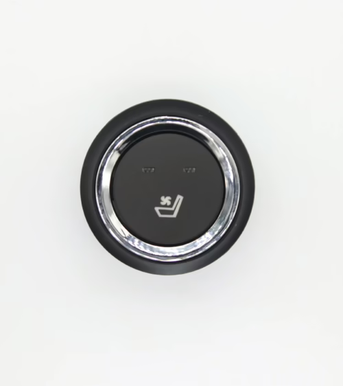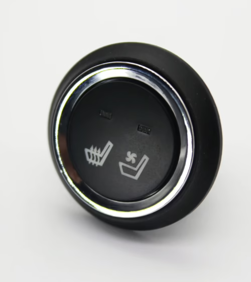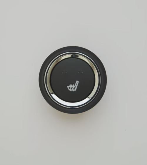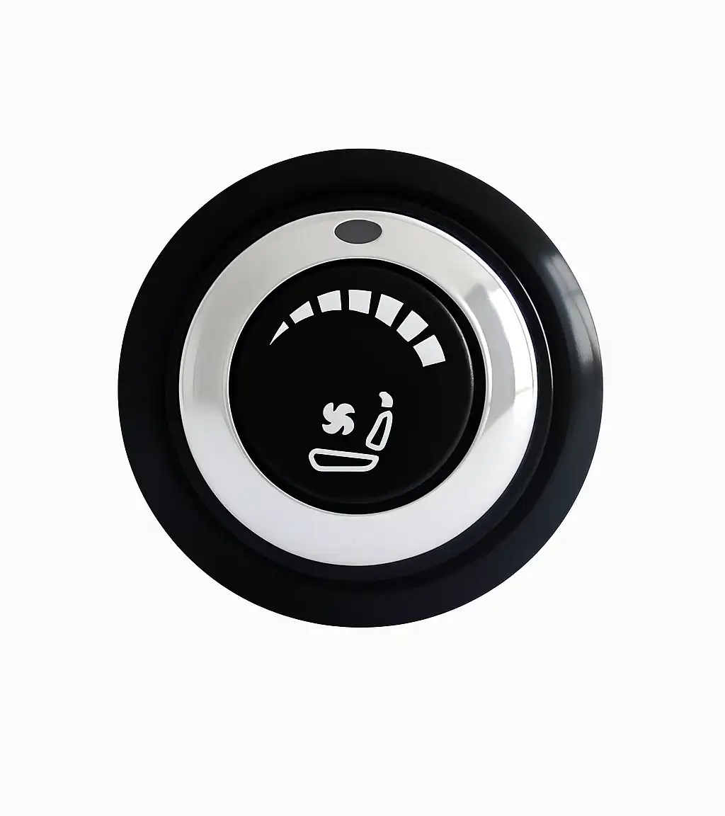
The seat heater rotary switch provides intuitive, stepwise control of seat heating level through a rotating knob mechanism that most vehicle occupants find easier to operate than push-button toggle switches. Understanding the engineering and sourcing considerations for a seat heater rotary switch — including electrical interface type, detent configuration, connector format, and IP sealing — is important for OEM engineers specifying switch assemblies for a new seat program and for aftermarket installers selecting a retrofit control interface.
This guide covers the complete specification, wiring, and installation picture for the seat heater rotary switch in production and aftermarket applications.
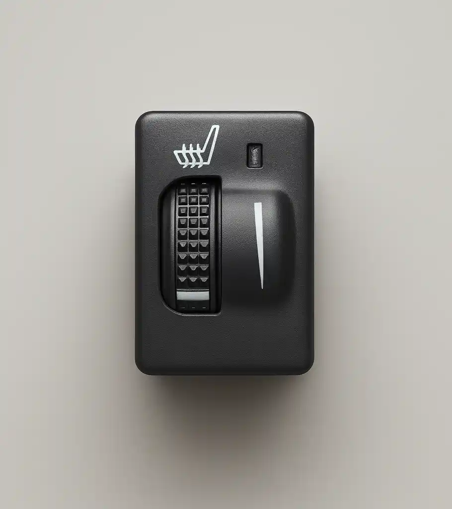
1. How a Seat Heater Rotary Switch Works
A seat heater rotary switch uses a rotating shaft that engages a series of detent positions — typically off plus three heat levels — to produce distinct switch states that the seat climate control module interprets as temperature setpoints. In the most common design, each detent position of the seat heater rotary switch connects a different resistor value in a resistor ladder network to the module switch sense input, producing a unique voltage that the module decodes as a specific command.
Some seat heater rotary switch designs use a binary-coded multi-pole switch where each detent closes a different combination of contacts, allowing four states to be encoded on three wires.
The detent mechanism in a seat heater rotary switch is engineered for tactile feedback — the force required to rotate between positions should be consistent, typically 0.3 to 0.6 Nm, and the feel of each detent should be firm enough to prevent accidental level changes during driving. Weak detents produce unintended position changes from vibration, which triggers unexpected temperature changes and generates warranty complaints for seat heater rotary switch assemblies in production programs.
2. Electrical Specifications for a Seat Heater Rotary Switch
A production seat heater rotary switch operates at 12 V nominal with a functional range of 9 to 16 V. Contact resistance at each switch position must be below 100 milliohms to prevent voltage drop errors on the sense line. Insulation resistance between switch positions and housing must exceed 10 megaohms at 500 V DC.
LED indicator illumination — if included in the seat heater rotary switch — draws 5 to 20 mA per indicator from a dedicated 12 V supply terminal separate from the switch sense circuit to prevent indicator current from affecting the sense voltage level.
The number of connector terminals on a seat heater rotary switch depends on the interface design. A four-position resistor ladder switch requires three terminals — common, sense, and LED supply. A binary-coded switch requires five terminals — common, two code outputs, ground, and LED supply. Confirm the terminal count and pinout before ordering a replacement seat heater rotary switch to avoid harness modification.
3. Detent Count and Heat Level Configuration
The standard configuration for a seat heater rotary switch in a production vehicle is four detent positions: off, low heat, medium heat, and high heat. Some vehicles use a three-position seat heater rotary switch — off, low, and high — omitting the medium level to simplify the control module firmware and reduce switch complexity.
Premium trim levels on some European platforms use a five-position seat heater rotary switch that adds a maximum heat position for extremely cold climates.
Aftermarket seat heater rotary switch assemblies for retrofit kits are most commonly three-position or four-position. Confirm the detent count matches the seat heater control module input decoder range — a three-position seat heater rotary switch installed on a module expecting four positions will not access the module fourth heat level setting, reducing the available comfort range for the end user.
4. IP Rating and Panel Mounting Requirements
A seat heater rotary switch installed in a center console or armrest panel is exposed to beverage spills, hand cream, and high humidity from occupant proximity. OEM programs specify a minimum IP54 rating for any seat heater rotary switch installation — protection against dust and splashing water. For switches mounted in open panel locations without a protective bezel, IP65 is preferred.
Panel mounting for a seat heater rotary switch uses a threaded bushing that passes through the panel cutout and is secured by a nut or snap ring on the back side of the panel. Cutout diameter for standard 22 mm seat heater rotary switch bodies is 20 to 21 mm.
Some OEM formats use a proprietary retaining clip rather than a threaded bushing — confirm the mounting method matches the panel design before beginning the seat heater rotary switch installation.
5. Wiring a Seat Heater Rotary Switch: Step-by-Step
Wiring an aftermarket seat heater rotary switch to a seat heater control module follows a consistent procedure. First, identify the switch sense input pin on the module connector using the wiring diagram supplied with the kit — it is usually labeled SW or SENSE. Second, connect the switch common terminal to the vehicle ground. Third, connect the switch sense output to the module SW input.
Fourth, connect the LED supply terminal to a switched 12 V source — usually the same source supplying the module VCC pin. Fifth, connect the module power and ground terminals and test all switch positions, confirming the correct heat level activation at each detent position of the seat heater rotary switch.
6. OEM vs. Aftermarket Seat Heater Rotary Switch Options
OEM seat heater rotary switch assemblies are designed for a specific vehicle platform and connector harness. They offer a perfect fit and finish match but are available only through dealership parts counters at significant cost premium. Aftermarket seat heater rotary switch assemblies offer broader compatibility through pigtail adapters and adjustable mounting hardware, at a fraction of the OEM replacement cost.
For retrofit programs where the switch will be installed in a new panel location, aftermarket seat heater rotary switch options provide more installation flexibility than OEM parts designed for a fixed panel cutout.
Frequently Asked Questions About Seat Heater Rotary Switches
Can I replace a push-button switch with a seat heater rotary switch?
Yes, if the seat heater control module accepts the same electrical signal type — discrete voltage levels or resistor ladder — that the seat heater rotary switch produces. Most aftermarket control modules support both interface types with jumper-selectable input configuration. Confirm the module wiring diagram before making the substitution from push-button to seat heater rotary switch.
Why does my seat heater rotary switch feel loose in one detent position?
Loose detent feel indicates worn detent ball springs or a deformed detent track in the switch mechanism, usually caused by forceful rotation. Replace the seat heater rotary switch assembly rather than attempting internal repair — switch mechanism components are not available separately from the complete assembly.
What is the difference between a 3-position and 4-position seat heater rotary switch?
A 3-position seat heater rotary switch provides off, low heat, and high heat — adequate for moderate climates where fine temperature adjustment is not critical. A 4-position seat heater rotary switch adds a medium heat level between low and high, giving occupants better control over comfort in a wider range of ambient temperatures.
Most OEM programs specify the 4-position seat heater rotary switch to maximize comfort range.
Source Seat Heater Rotary Switches from Lucky Driver Inc.
Lucky Driver Inc. supplies seat heater rotary switch assemblies in three-position and four-position configurations to OEM seat manufacturers and aftermarket distributors across North America. Each seat heater rotary switch includes installation hardware, a wiring pigtail with color-coded conductors, and a detailed wiring diagram. Contact Lucky Driver Inc. to request seat heater rotary switch samples or pricing for your program requirements.
Seat Heater Rotary Switch: Summary
A correctly specified seat heater rotary switch delivers reliable, intuitive heat level control with a tactile detent feel that meets occupant expectations and control module input requirements. Lucky Driver Inc. stocks seat heater rotary switch assemblies for OEM and aftermarket programs, with engineering support available for custom interface configurations and panel mounting requirements. Contact us to begin your seat heater rotary switch sourcing process.
Further Reading
Technical Glossary
NTC Thermistor: Negative Temperature Coefficient resistor used as the temperature feedback sensor in seat climate systems. Resistance decreases predictably as temperature rises, allowing the control module to calculate surface temperature and adjust duty cycle.
PWM (Pulse Width Modulation): The seat heater module switches the element circuit on and off at high frequency, varying the on-time ratio between 0% and 100% to achieve any intermediate power level without resistive loss in a series regulator.
LIN Bus: Low-speed serial protocol used in automotive seat climate systems for communication between the seat module and body control module. Operates at 20 kbit/s over a single wire, enabling infotainment-screen control and OBD-II fault code reporting.
IP54 Rating: Minimum ingress protection for seat climate components. The first digit (5) indicates dust protection; the second (4) indicates resistance to water splash from any direction — required for components exposed to beverage spills.
CISPR 25 Class 5: Most stringent automotive radiated and conducted emissions limit. Switching noise from heater PWM circuits must remain below defined limits from 0.15 MHz to 1 GHz to prevent audible AM radio interference.
PPAP: Production Part Approval Process. Requires dimensional reports, material certifications, and process capability data before a component enters production at an OEM facility. Most Tier-1 seat suppliers require full PPAP from upstream component suppliers before sourcing approval is granted.
Industry Standards and Compliance Reference
ISO 16750: Environmental conditions and testing for electrical and electronic equipment in road vehicles. Defines temperature cycling, humidity, vibration, and shock test profiles that seat climate components must survive without performance degradation or connector failure during a vehicle lifetime of 15 years or 240,000 kilometers.
SAE J1772: While primarily an EV charging standard, the 12 V auxiliary power architecture defined in SAE J1772 governs the operating voltage envelope that automotive seat accessories must tolerate — nominal 12 V, range 9–16 V, transient spikes to 24 V for 50 ms under load-dump conditions.
REACH and RoHS Compliance: European Union regulations restricting hazardous substances in electrical equipment. REACH limits 224 substances of very high concern (SVHCs). RoHS restricts lead, mercury, cadmium, hexavalent chromium, and four phthalates. OEM customers increasingly require full REACH and RoHS compliance declarations before approving suppliers.
IATF 16949:2016: Automotive quality management system standard derived from ISO 9001, adding automotive-specific requirements including control plans, process FMEA, production part approval, and customer-specific requirements. Tier-1 seat manufacturers typically require sub-tier component suppliers to hold IATF 16949 certification or to operate under an approved quality agreement.
UL 94 V-0 Flammability: Polymer components used in seat climate systems must meet UL 94 V-0 flammability classification — the specimen must self-extinguish within 10 seconds of flame removal, with no dripping of burning particles. This applies to connector housings, wire insulation jacketing, and control module enclosures.
Wiring Reference for 3-Speed Rotary Controls
Terminal Function Overview: A standard 3-position rotary controller uses five terminals: battery positive input, ground, and three switched outputs — one for each heat level. Terminal labeling varies by manufacturer, but the convention is: B+ for battery, GND for ground, L1 for low heat, L2 for medium heat, L3 for high heat.
Current Rating: The total current through the control is the sum of all pad circuits it manages. A dual-zone system (bottom cushion plus backrest) with 4 A per zone draws 8 A total. Specify a control rated to at least 10 A to maintain a 25% design margin against resistive heating of internal contacts.
Wire Gauge Selection: Feed wires carrying the full load current to the switch must be sized accordingly. At 10 A on a 12 V circuit, use minimum 18 AWG for runs under 1.5 m; use 16 AWG for longer runs or where ambient temperatures exceed 60°C near engine heat sources.
Fuse Protection: Install an inline fuse within 45 cm of the battery positive connection, sized to 125–150% of the maximum expected load. A 15 A fuse protects a 10 A load while allowing brief inrush current at startup without nuisance tripping.
Relay Recommendations: For high-current applications above 15 A, wire the control through a relay rather than switching load current directly through the rotary control contacts. The control switches only the relay coil (low current, typically 150–200 mA), and the relay contacts handle the full pad current load. This extends rotary control service life significantly in high-cycle applications.
Ground Path Quality: All heating element ground returns should share a single dedicated ground point bolted directly to the seat frame or vehicle chassis — not daisy-chained through connector grounds. A shared, low-resistance ground path prevents differential voltage offsets between zones that can cause erratic thermostat behavior.
Frequently Asked Questions
Q: Can I install a new 3-speed control without removing the seat?
A: Yes, in most cases. The existing wiring harness typically extends 300–500 mm from the seat base, providing enough slack to reach the control while it remains in the vehicle. Disconnect the battery first, unplug the existing harness connector, and bench-test the replacement unit with a 12 V bench supply before reinstalling.
Q: What causes the control to feel hot after extended use?
A: A warm control housing is normal — internal contacts dissipate a small amount of resistive heat proportional to load current. A control that is too hot to touch indicates either a loose connection creating arc resistance, a current load exceeding the contact rating, or a failing internal contact that requires replacement.
Q: Will a higher IP-rated version work in a wet environment such as a marine or agricultural vehicle?
A: Yes. For open-cab tractors, marine vessels, and other environments where the control may be exposed to splash water or condensation, specify a version with IP54 or IP65 rating. Standard IP40 controls are only suitable for covered cabin environments where direct liquid contact is not expected.
Q: Can the same control manage both a cushion heater and a backrest heater simultaneously?
A: Yes, provided the combined current draw of both zones does not exceed the contact current rating. Wire both element circuits in parallel from the switched output terminal. Calculate total load: two 4 A zones equal 8 A total, requiring a control rated for at least 10 A.
Need the hardware itself? Browse our seat heater switch catalog with US-based shipping.
Related Articles
- How to Add Heated Seats to Any Car: 5-Step Aftermarket Installation Guide
- Seat Heater Switch Replacement: Identification, Sourcing, and Installation Guide
- Seat Ventilation System: How It Works, Components, and OEM Sourcing Guide
- How to Choose an Automotive Seat Heater Supplier: 7 Qualification Criteria