Who Is The Lucky Driver?
The Lucky Driver is the brand name behind one of North America’s most reliable aftermarket and OEM-supply lines of automotive seat heating and ventilation components.
Whether you are a seat manufacturer integrating a new thermal comfort system into a commercial vehicle program, or a service technician replacing a failed component on a customer’s daily driver, the Lucky Driver product lineup is built to cover both use cases with traceable engineering specs and fast fulfillment.
This guide breaks down every major technical element of heated seat systems — resistive elements, switches, control modules, and ventilation — so you can diagnose, specify, and install with precision.
How Resistive Seat Heater Elements Work
Seat heater pads use resistive heating technology:
- a carbon fiber or carbon-alloy resistance wire is laminated between layers of non-woven polyester fabric
- producing a thin
- flexible mat that conforms closely to seat foam geometry. When current flows through the element
- electrical resistance converts energy into heat according to Joule’s law (P = I²R). Heating elements in automotive applications must balance fast warm-up response — typically reaching target surface temperature within 60 seconds — against long-term durability across hundreds of thousands of thermal cycles.
Element power density is specified in watts per square meter. A standard front seat cushion element typically runs between 35 W and 55 W total, while a backrest element falls in the 25 W to 40 W range.
Full-seat systems are designed to draw no more than 8–10 A at 12 V to stay within typical automotive fuse ratings. Lucky Driver seat heater pads are manufactured to dimensional tolerances aligned with SAE J1759, ensuring compatibility with standard OEM foam profiles across leading vehicle platforms.
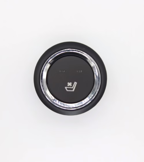
The Seat Heater Switch: Interface and Failure Points
The seat heater switch is the primary control interface between the vehicle occupant and the thermal system. It sends a low-current logic signal to a relay, MOSFET driver, or dedicated seat heater control module, selecting the active heat level.
Most production designs use a three-position momentary rocker or illuminated push-button that cycles through OFF → LOW → HIGH → OFF on each actuation. The switch itself carries only the control-signal current; high-current load paths are handled downstream by a relay or solid-state switching stage.
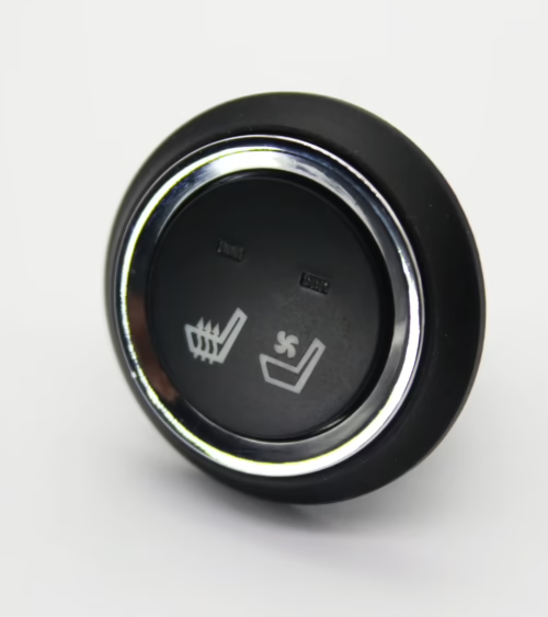
Switch failure accounts for the largest share of heated seat complaints in the field. Common failure modes include contact oxidation from moisture ingress, UV embrittlement of the switch housing, and mechanical wear on the detent mechanism.
When sourcing replacements, browse our seat heater switch catalog for verified OEM-compatible options covering Ford, GM, Honda, Toyota, and other major platforms — each unit tested for contact resistance below 50 mΩ and rated for at least 50,000 actuation cycles.
Seat Heater Control Modules: Closed-Loop Temperature Management
In vehicles with integrated body electronics, a dedicated seat heater control module (SHCM) replaces the simple relay found in basic systems.
The SHCM reads the switch input, monitors one or two NTC thermistors embedded in the seat foam, and drives the heating element through a PWM output — typically at a carrier frequency between 200 Hz and 1 kHz.
This closed-loop regulation holds seat surface temperature within approximately ±3°C of the set point without running the element at continuous full power.
- Low heat setting: PWM duty cycle of 40–55%, targeting a surface temperature around 36–38°C.
- High heat setting: PWM duty cycle of 70–85%, targeting a surface temperature around 42–45°C.
- Overheat cutoff: Module disables output if the thermistor exceeds 55°C, preventing occupant burn risk.
- Diagnostic output: CAN-bus integrated modules log DTCs readable by standard OBD-II scan tools.
Lucky Driver control modules support both standalone relay-based harnesses and CAN-bus architectures. All units are validated across the full automotive operating temperature range of -40°C to +85°C and carry a minimum 12-month warranty against manufacturing defects.
Seat Ventilation Systems: Thermal Comfort Beyond Winter
Seat ventilation extends the value of thermal seating systems into warm-weather months. A centrifugal blower — typically rated at 12 V and 1.5 A to 3 A draw — mounts beneath the seat cushion or within the seat back and pulls air through a perforated leather or breathable fabric surface.
This active airflow removes body heat and perspiration from the occupant-seat interface, dramatically reducing thermal discomfort during summer driving.
In dual-function seats, the same ventilation architecture can distribute heated air from the element mat at low temperatures, improving warm-up efficiency and reducing element power consumption.
Key performance parameters to specify when selecting a ventilation system include airflow rate (typically 3–8 CFM per zone), acoustic noise level (target below 38 dBA measured at 1 m in free-field conditions), and ingress protection rating against liquid spills.
Lucky Driver ventilation kits ship as complete assemblies including the blower motor, foam diffuser ducting, and an integrated or standalone controller compatible with existing seat wiring harnesses.
OEM vs. Aftermarket Seat Heater Components: What to Evaluate
OEM seat heater parts carry brand-name pricing and dealer-channel lead times that often make aftermarket sourcing the practical choice for shops and fleet operators. The key is evaluating whether an aftermarket alternative genuinely meets engineering requirements — not just approximate dimensions. Critical specification checkpoints include:
- Element resistance tolerance: Must be within ±5% of the OEM nominal value to maintain correct current draw and warm-up curve.
- Connector format: Plug-and-play OEM-style connectors eliminate field splicing and reduce the risk of high-resistance joints.
- Material certification: RoHS compliance is a baseline requirement; OEM seat programs typically also require REACH substance declarations.
- Cycle life testing: Demand third-party or in-house data showing element and switch durability through the rated service life.
Lucky Driver components are benchmarked against OEM samples using a standardized protocol that includes four-wire resistance measurement, thermal imaging under load, 10,000-cycle mechanical switch endurance, and connector pull-force verification.
To review the complete lineup before ordering, explore all seat heating products in our full product shop and filter by vehicle application or component category.
Step-by-Step Diagnosis for a Failed Seat Heater System
A disciplined diagnostic sequence prevents unnecessary parts replacement and reaches root cause faster. Use this approach when a heated seat fails to operate or only functions on one heat level:
- Step 1 — Fuse check: Locate the seat heater fuse in the under-dash or engine bay fuse block. A blown fuse points to a downstream short circuit, not a switch fault.
- Step 2 — Switch continuity test: Disconnect the switch harness connector and probe pin-to-pin continuity through each switch position with a multimeter in resistance mode. Compare readings to the wiring diagram.
- Step 3 — Supply voltage verification: With the ignition on, confirm 12 V at the switch power input pin. Absence of voltage indicates an open circuit upstream — fuse, relay, or wiring fault.
- Step 4 — Connector inspection: Corroded, oxidized, or backed-out terminals account for a significant proportion of intermittent failures. Clean terminals with electrical contact cleaner and fully reseat each pin.
- Step 5 — Element resistance measurement: Disconnect the heating element connector and measure resistance directly. Typical values range from 2 Ω to 6 Ω for a cushion element. An open circuit reading confirms element failure.
- Step 6 — Substitute and confirm: Swap in a known-good replacement switch or element to confirm the faulty component before closing the repair.
Physical switch replacement on most platforms takes 15 to 30 minutes:
- the switch panel unclips from the seat side trim or center console
- the connector unplugs
- the new unit installs in reverse order. Relay-based systems require no module programming
- CAN-bus systems typically need one ignition cycle for the SHCM to recognize the newly installed component.
FAQ: Your Seat Heater Questions Answered
Q: Can I retrofit seat heaters into a vehicle that was not factory-equipped with them?
A:
- Yes. Complete retrofit kits include the element mat
- NTC thermistor
- controller or thermostat
- switch
- wiring harness. Installation involves removing the seat upholstery
- adhering the element mat to the foam surface
- routing the harness to the switch location
- connecting to a switched 12 V circuit through an appropriately rated fuse. An experienced installer can complete a front-seat pair in three to five hours with no module coding required on standalone harness designs.
Q: Why does my seat heater stay at maximum temperature even on the low setting?
A:
- Continuous high output on the low setting is almost always caused by a failed NTC thermistor. When the thermistor circuit opens
- the control module loses temperature feedback and defaults to maximum PWM duty cycle. Replace the thermistor first — it is the lower-cost component — and retest before condemning the module. If the bench resistance of the thermistor reads correctly (typically 10 kΩ at 25°C for a standard NTC sensor)
- suspicion shifts to the module logic board.
Q: What is the difference between a seat heater thermostat and a seat heater control module?
A:
- A thermostat is a simple bimetallic or PTC snap-disc device that mechanically opens the heating circuit at a fixed cutoff temperature — typically 60–70°C — and resets automatically when the element cools. It offers no PWM regulation and no diagnostic output.
- A seat heater control module is a full electronic assembly that continuously reads thermistor input
- adjusts PWM duty cycle in real time
- on CAN-integrated platforms communicates status to the body control module. Modules deliver tighter temperature regulation
- multi-level heat settings
- service data
- thermostats are lower cost but provide only binary overheat protection.
Lucky Driver Inc. is your North American source for engineered seat heater pads, switches, control modules, and ventilation systems — serving OEM seat manufacturers, automotive distributors, and professional technicians across the continent.
Every product in our catalog is tested to specification before shipment, backed by a warranty, and supported by a technical team ready to confirm compatibility and advise on installation. Visit our website or contact us directly to find the exact seat heater solution your application requires.
Related Articles
- Ford Explorer Seat Heater Switch: 2026 Complete Repair Guide
- Ford F150 Heated Seat Switch: 2026 Complete Repair Guide
- Honda Pilot Heated Seat Switch: 2026 Complete Repair Guide
- Honda CR-V Seat Heater Switch: 2026 Complete Repair Guide
- Honda Accord Heated Seat Switch: 2026 Repair Guide
Frequently Asked Questions About the lucky driver
Procurement engineers evaluating the lucky driver for OEM programs regularly ask the following questions. Answers cover specification, compatibility, certification, and sourcing for the lucky driver requirements.
What voltage ratings are available for the lucky driver?
Standard the lucky driver configurations support 12 V DC for passenger vehicles and 24 V DC for commercial trucks. Selecting the correct the lucky driver voltage at the design stage eliminates harness rework later. Lucky Driver maintains the lucky driver inventory in both ratings for same-week shipment.
Which certifications apply to the lucky driver production?
the lucky driver assemblies entering OEM programs typically require UL recognition, REACH compliance, and RoHS documentation. Lucky Driver holds certification records for every the lucky driver variant and includes copies with sample and production shipments.
How is watt density specified for the lucky driver?
Watt density for the lucky driver is expressed in W/cm² and ranges from 0.04 to 0.12 depending on heat-up time requirements. Lower watt density the lucky driver designs improve element longevity, while higher values suit cold-climate applications.
Lucky Driver engineering reviews the lucky driver requirements and recommends watt density based on your seat platform.
What connector families are used with the lucky driver?
the lucky driver harnesses are available with Molex, TE Connectivity, and Delphi connector families. Matching the the lucky driver connector to the vehicle harness reduces assembly time and eliminates adapter cables. Specify your harness format when requesting a the lucky driver quote from Lucky Driver.
What is the lead time for the lucky driver samples?
the lucky driver samples from Lucky Driver’s North American warehouse ship within 3 to 5 business days for standard configurations. Custom the lucky driver variants with modified pad geometry or connector pinouts require 4 to 6 weeks. Contact Lucky Driver to confirm the lucky driver availability before submitting your engineering schedule.